Coupling strategies for ultra-high field dielectric resonators
- 1. Pennsylvania State University, Huck Institutes of the Life Sciences, University Park, United States
- 2. Pennsylvania State University, Material Research Institute, University Park, United States
- 3. Pennsylvania State University, Engineering Science and Mechanics, University Park, United States
Introduction: Recently cylindrical dielectric resonators (CDR) have been used instead of traditional RF coils in MRI probes at high-field strength (B0 ≥ 7T) [1] [2] [3] [4] [5]. However, the optimal coupling scheme for the CDRs in not yet explored. In this study, different coupling methods for TE01 δ mode were investigated and compared using S parameters.
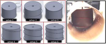
Methods: A cylindrical hollow bore dielectric resonator made of ceramic CaTiO3 (rel. permittivity of 156) with a Q-factor of 2225 was used in TE01δ mode to create a MRI probe head for 14 Tesla. Five coupling methods (totally 6 setups) were evaluated (see Fig. 1). The CDR was placed in a copper shield during all the evaluations of these coupling methods and a sensor probe was placed in the bore center of the CDR to measure the S21 and its Q-factor using a network analyzer. [6]

| Setup | S21 | Q-factor |
| 1 | -20.0dB | |
| 2 | -15.0dB | 108.5 |
| 3 | -11.9dB | 253.7 |
| 4 | -13.3dB | 179.5 |
| 5 | -9.2dB | 716.2 |
| 6 | -9.9dB | 393.2 |
Results: The Q-factors and their S21 values of five coupling methods are presented in Table 1. By replacing a small coupling loop on aside of the resonator with a large coupling loop surrounding the resonator, we were able to increase the S21 value with a sacrifice in Q-factor, which means a gain in B1+ field strength with a trade-off in SNR. Overall, the triple loop yielded the best coupling scheme with a Q-factor around 716.2 and S21 value of -9.20 dB.
Discussions: The measured Q-factors shown in Tab 1 are related to other contributions in the resonant system as 1/Q =1/Qc+1/Qd+ 1/Qrad+1/Qex, where Qc, Qd, Qrad, and Qex, are the Q-factors that are due to losses in conductor, dielectric, radiation, and external circuitry. The Qex value decreases when the external coupling increases, so there is a trade-off between S21 and Qex [6] [7] . By using large and multi-turn loops, we managed to balance the effects of coupling on Qex with the additional contributions Qc, and Qrad. Such that, the S21 value was improved by 91.7% with the Q-factor decrease of 34.6%.
- [1] Haines et al, (2009), High Q calcium titanate cylindrical dielectric resonators for magnetic resonance microimaging., 200:349-53
- [2] Neuberger et al, (2008), Design of a ceramic dielectric resonator for NMR microimaging at 14.1 tesla, CONCEPT MAGN RESON B, 33B:109-14
- [3] Aussenhofer et al, (2012), Design and evaluation of a detunable water-based quadrature HEM11 mode dielectric resonator as a new type of volume coil for high field MRI., MRM, 4):1325-31.
- [4] Aussenhofer et al, (2013), High-permittivity solid ceramic resonators for high-field human MRI., NMR Biomed, 26:1555-61
- [5] Aussenhofer et al, (2014), An eight-channel transmit/receive array of TE01 mode high permittivity ceramic resonators for human imaging at 7T., JMR, 243:122-9.
- [6] Pozar, D, (1998), Microwave engineering
- [7] Kajfez, D, (1994), Q Factor.
