Susceptibility artefacts of thin film platinum electrodes
- 1. Karlsruhe Institut für Technologie, Institut für Mikrostrukturtechnik, Eggenstein-Leopoldshafen, Germany
- 2. University Medical Center Freiburg, Department of Radiology - Medical Physics, Freiburg, Germany
- 3. University of Freiburg, Department of Microsystems Engineering - IMTEK, Freiburg, Germany
Motivation: The rapidly growing number of patients with neuronal implants [1] increases the necessity to characterize the interaction of these implants with the magnetic resonance (MR) environment. Interactions such as susceptibility artefacts can lead to a loss of information in regions close to implants and will be a larger problem in future medical MR examinations in terms of misinterpretation of the acquired data. Here, we focus on characterizing the interaction of the static magnetic field (B0) with thin film platinum electrodes [2].
Fundamentals & Simulation:
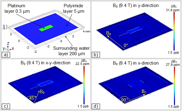
Materials placed inside a magnetic field induce a distortion of the static magnetic field. During an MR imaging examination non-correctable B0 distortions result in a loss of information, i.e., in an artefact. To predict such distortions an FEM simulation was conducted.

Figure 1a shows the geometrical arrangement of the simulation setup. B0 is parallel to the x-y-plane but varies in three steps from 0° to 90° w.r.t. y-axis (Figure 1b -1d). The most artefacts can be seen when B0 is perpendicular to the material transition interfaces and the least when B0 is parallel.
Experimental verification:
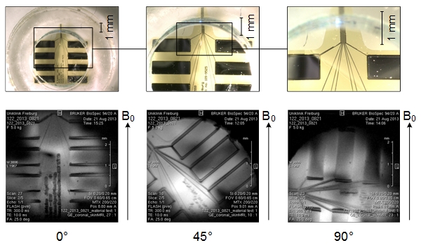
To verify the simulation results an MR measurement of the platinum electrodes was conducted, with the electrode aligned in three orientations in the plane. The electrode was mounted in a PMMA container and immersed in doped water (CuSO4 1 g/l), to reduce the T1 relaxation time. The data was acquired using a phased array of micro-coils [3].

Figure 2 shows the results of the MRI examinations. The magnitude of the B0 deviations depends on the orientation of the electrode inside the magnetic field. Signal loss can be observed at the material transition interfaces with increasing angle w.r.t. B0.
Conclusion:
Thin film platinum layers create artefacts that depend on the orientation w.r.t. B0. The experiments confirm the results of the simulation. The acquired MR images depend on the orientation of the electrode within B0, which causes potentially severe problems with the interpretation of data.
Acknowledgements:
Funded within the Cluster of Excellence "BrainLinksBrainTools" by the German Research Foundation (DFG ExC1086).
- [1] Lim, H. et al. , (2015), Auditory midbrain implant: Research and development towards a second clinical trial, Hearing Research, 212-223, www.sciencedirect.com/science/article/pii/S0378595515000106
- [2] Rubehn B. et al., (2009), A MEMS-based flexible multichannel ECoG-electrode array, Journal of neural engineering, http://iopscience.iop.org/1741-2552/6/3/036003/
- [3] Gruschke, O.G. et al., (2012), Lab on a chip phased-array MR multi-platform analysis system, Lab on a chip, http://www.ncbi.nlm.nih.gov/pubmed/22200053
