A Detail Design of Active Broadband Duplexer for Low-field NMR
- 1. State Key Laboratory of Petroleum Resource and Prospecting, China University of Petroleum, Beijing, China
- 2. Sinopec Research Institute of Petroleum Engineering, Sinopec, Beijing, China
In low-field NMR, a single coil is employed to transmit high voltage RF pulse and to receive the weak echo signals. Therefore, a duplexer circuit is needed to isolate the receiver from the transmitter. In previous work, a based-on crossed diode pairs and quarter-wavelength line duplexer [1] is usually used in high-field NMR. Gibson presented π network equal to quarter-wave length line [2] in the low-field NMR, but the frequency is narrow. It is not convenient to change the duplexer circuit for different frequency ranges. Recently, a broadband duplexer relying on actively-controlled switches [3] was presented. This technique used the H-bridge to change the VGS of the FET and have a good effect.
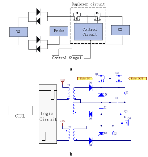
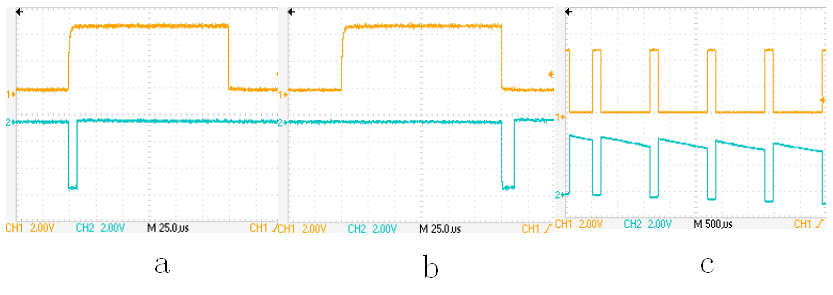
Here we present another new detail design of active broadband duplexer which is used in a spectrometer working from 2 to 25 MHz. As show in Fig.1, it consists of two FET switches connected back to back that isolate the receiver when the transmitter is ON, and a pair of cross-coupled diodes that isolate the transmitter from the coil when it is OFF. When the control signal is valid, logic circuit generates two negative pulses (Fig. 2(a)(b)) at the edge of the control signal. The first negative pulse makes the VGS of Q1, Q2 zero, so the Q1, Q2 are turned off. The second negative pulse makes the VGS of Q1, Q2 positive, so the Q1, Q2 are turned on(Fig.2(c)).The system works properly with this duplexer at the 100w transmitter's power from 2 to 25MHz. The noise figure measured at spots between 2 and 25 MHz is at most 3 dB. We would do some more research on the effect of the Ron and CGS of the FET to get better at it.


- [1] I J Lowe , C E Tarr, (1968), A fast recovery probe and receiver for pulsed nuclear magnetic resonance spectroscopy, Journal of Scientific Instruments
- [2] P Cofrancesco, G Moiraghi, P Mustarelli , M Villa, (1991), A new NMR duplexer made with quadrature couplers
- [3] S Mandal, S Utsuzawa, DG Cory, M Hürlimann, M. Poitzsch, Y.-Q. Song, (2014), An ultra-broadband low-frequency magnetic resonance system
